- 您现在的位置:买卖IC网 > Sheet目录3884 > PIC16F628T-04E/SO (Microchip Technology)IC MCU FLASH 2KX14 18-SOIC
PIC16F627A/628A/648A
DS40044G-page 138
2009 Microchip Technology Inc.
17.2
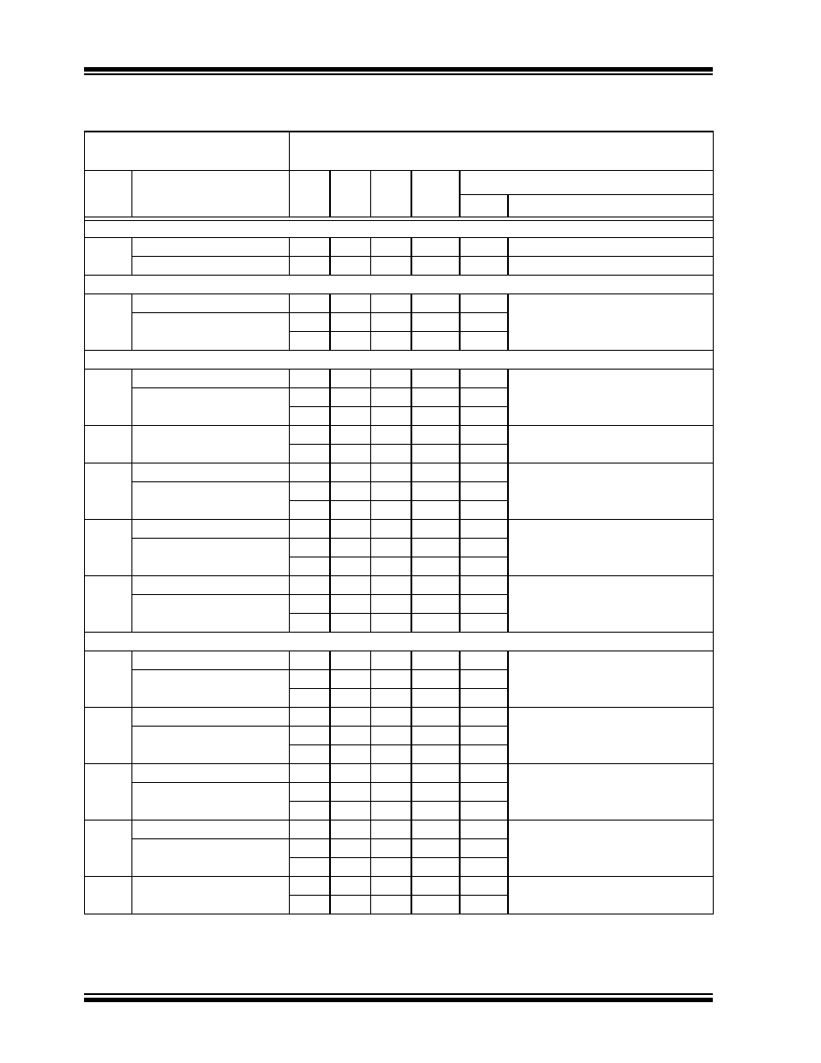
DC Characteristics: PIC16F627A/628A/648A (Industrial)
PIC16LF627A/628A/648A (Industrial)
DC CHARACTERISTICS
Standard Operating Conditions (unless otherwise stated)
Operating temperature
-40
°C ≤ Ta ≤ +85°C for industrial
Param
No.
LF and F Device
Characteristics
Min
Typ
Max
Units
Conditions
VDD
Note
Supply Voltage (VDD)
D001
LF
2.0
—
5.5
V
—
LF/F
3.0
—
5.5
V
—
Power-down Base Current (IPD)
D020
LF
—
0.01
0.80
μA
2.0
WDT, BOR, Comparators, VREF and
T1OSC: disabled
LF/F
—
0.01
0.85
μA3.0
—0.02
2.7
μA5.0
Peripheral Module Current (
ΔIMOD)(1)
D021
LF
—
1
2.0
μA
2.0
WDT Current
LF/F
—
2
3.4
μA3.0
—9
17.0
μA5.0
D022
LF/F
—
29
52
μA
4.5
BOR Current
—30
55
μA5.0
D023
LF
—
15
22
μA
2.0
Comparator Current
(Both comparators enabled)
LF/F
—
22
37
μA3.0
—44
68
μA5.0
D024
LF
—
34
55
μA2.0
VREF Current
LF/F
—
50
75
μA3.0
—80
110
μA5.0
D025
LF
—
1.2
2.0
μA2.0
T1OSC Current
LF/F
—
1.3
2.2
μA3.0
—1.8
2.9
μA5.0
Supply Current (IDD)
D010
LF
—
10
15
μA2.0
FOSC = 32 kHz
LP Oscillator Mode
LF/F
—
15
25
μA3.0
—28
48
μA5.0
D011
LF
—
125
190
μA2.0
FOSC = 1 MHz
XT Oscillator Mode
LF/F
—
175
340
μA3.0
—
320
520
μA5.0
D012
LF
—
250
350
μA2.0
FOSC = 4 MHz
XT Oscillator Mode
LF/F
—
450
600
μA3.0
—
710
995
μA5.0
D012A
LF
—
395
465
μA2.0
FOSC = 4 MHz
INTOSC
LF/F
—
565
785
μA3.0
—
0.895
1.3
mA
5.0
D013
LF/F
—
2.5
2.9
mA
4.5
FOSC = 20 MHz
HS Oscillator Mode
—2.75
3.3
mA
5.0
Note 1:
The “
Δ” current is the additional current consumed when this peripheral is enabled. This current should be
added to the base IDD or IPD measurement. Max values should be used when calculating total current
consumption.
发布紧急采购,3分钟左右您将得到回复。
相关PDF资料
PIC18F448T-I/L
IC MCU FLASH 8KX16 W/CAN 44-PLCC
PIC18LF448T-I/L
IC MCU FLASH 8KX16 LV CAN 44PLCC
PIC18LF458T-I/L
IC MCU FLSH 16KX16 LV CAN 44PLCC
PIC16F627-04E/P
IC MCU FLASH 1KX14 18-DIP
PIC16F627-20E/P
IC MCU FLASH 1KX14 18-DIP
PIC16C54C-20I/P
IC MCU OTP 512X12 18DIP
PIC16F627T-04E/SO
IC MCU FLASH 1KX14 18-SOIC
PIC18LF448-I/L
IC PIC MCU FLASH 8KX16 44PLCC
相关代理商/技术参数
PIC16F628T-04E/SS
功能描述:8位微控制器 -MCU 3.5KB 224 RAM 16 I/O RoHS:否 制造商:Silicon Labs 核心:8051 处理器系列:C8051F39x 数据总线宽度:8 bit 最大时钟频率:50 MHz 程序存储器大小:16 KB 数据 RAM 大小:1 KB 片上 ADC:Yes 工作电源电压:1.8 V to 3.6 V 工作温度范围:- 40 C to + 105 C 封装 / 箱体:QFN-20 安装风格:SMD/SMT
PIC16F628T-04I/SO
功能描述:8位微控制器 -MCU 3.5KB 224 RAM 16 I/O RoHS:否 制造商:Silicon Labs 核心:8051 处理器系列:C8051F39x 数据总线宽度:8 bit 最大时钟频率:50 MHz 程序存储器大小:16 KB 数据 RAM 大小:1 KB 片上 ADC:Yes 工作电源电压:1.8 V to 3.6 V 工作温度范围:- 40 C to + 105 C 封装 / 箱体:QFN-20 安装风格:SMD/SMT
PIC16F628T-04I/SS
功能描述:8位微控制器 -MCU 3.5KB 224 RAM 16 I/O RoHS:否 制造商:Silicon Labs 核心:8051 处理器系列:C8051F39x 数据总线宽度:8 bit 最大时钟频率:50 MHz 程序存储器大小:16 KB 数据 RAM 大小:1 KB 片上 ADC:Yes 工作电源电压:1.8 V to 3.6 V 工作温度范围:- 40 C to + 105 C 封装 / 箱体:QFN-20 安装风格:SMD/SMT
PIC16F628T-20/SO
功能描述:8位微控制器 -MCU 3.5KB 224 RAM 16 I/O RoHS:否 制造商:Silicon Labs 核心:8051 处理器系列:C8051F39x 数据总线宽度:8 bit 最大时钟频率:50 MHz 程序存储器大小:16 KB 数据 RAM 大小:1 KB 片上 ADC:Yes 工作电源电压:1.8 V to 3.6 V 工作温度范围:- 40 C to + 105 C 封装 / 箱体:QFN-20 安装风格:SMD/SMT
PIC16F628T-20/SS
功能描述:8位微控制器 -MCU 3.5KB 224 RAM 16 I/O RoHS:否 制造商:Silicon Labs 核心:8051 处理器系列:C8051F39x 数据总线宽度:8 bit 最大时钟频率:50 MHz 程序存储器大小:16 KB 数据 RAM 大小:1 KB 片上 ADC:Yes 工作电源电压:1.8 V to 3.6 V 工作温度范围:- 40 C to + 105 C 封装 / 箱体:QFN-20 安装风格:SMD/SMT
PIC16F628T-20E/SO
功能描述:8位微控制器 -MCU 3.5KB 224 RAM 16 I/O RoHS:否 制造商:Silicon Labs 核心:8051 处理器系列:C8051F39x 数据总线宽度:8 bit 最大时钟频率:50 MHz 程序存储器大小:16 KB 数据 RAM 大小:1 KB 片上 ADC:Yes 工作电源电压:1.8 V to 3.6 V 工作温度范围:- 40 C to + 105 C 封装 / 箱体:QFN-20 安装风格:SMD/SMT
PIC16F628T-20E/SS
功能描述:8位微控制器 -MCU 3.5KB 224 RAM 16 I/O RoHS:否 制造商:Silicon Labs 核心:8051 处理器系列:C8051F39x 数据总线宽度:8 bit 最大时钟频率:50 MHz 程序存储器大小:16 KB 数据 RAM 大小:1 KB 片上 ADC:Yes 工作电源电压:1.8 V to 3.6 V 工作温度范围:- 40 C to + 105 C 封装 / 箱体:QFN-20 安装风格:SMD/SMT
PIC16F628T-20I/SO
功能描述:8位微控制器 -MCU 3.5KB 224 RAM 16 I/O RoHS:否 制造商:Silicon Labs 核心:8051 处理器系列:C8051F39x 数据总线宽度:8 bit 最大时钟频率:50 MHz 程序存储器大小:16 KB 数据 RAM 大小:1 KB 片上 ADC:Yes 工作电源电压:1.8 V to 3.6 V 工作温度范围:- 40 C to + 105 C 封装 / 箱体:QFN-20 安装风格:SMD/SMT